
Optical isolator module driver#
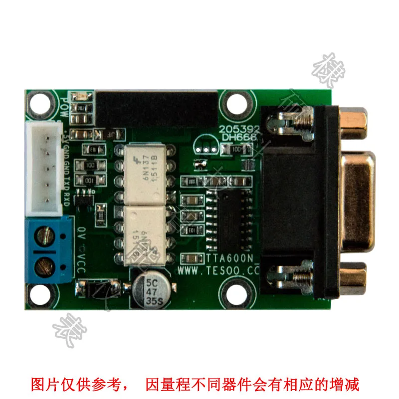
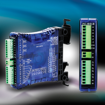
This Optical Isolator can help clean up noisy signals by converting to a different line driver output. Up to eight Optical Isolator Modules can be daisy-chained to provide multiple, simultaneous outputs to controllers or PLC’s. It accommodates all standard operating voltages from 5 to 28 VDC. It accepts single ended or differential inputs and provides single ended or differential outputs in either an open collector or line driver configuration. This is a versatile interface between an incremental encoder and receiving electronics. is required for the manufacturing of Butterfly Module, Optical Pump Module and other type of modules. SIGNAL: Specifying an optical isolator module requires knowledge of three system parameters: the DC supply voltage available in the system the encoder output type (logic levels and driver type) and the input signal specifications of the receiving electronics.

Any encoders used in conjunction with this module must be connected to their own power. The optical isolator module does not provide power to the encoder. The module draws approximately 75 mA and a green LED indicates the unit is powered. It should never be connected directly to AC power mains. POWER: The optical isolator can accommodate standard operating voltages from 5 to 28 VDC. The module simply snaps directly to the DIN rail and is ready to use. A length of DIN rail is supplied with each module. The package mounts to a DIN rail type EN 50 022 (35mm X 7.5mm). Package dimensions are 114.4 mm high by 99 mm wide by 22.5 mm thick. Voltage: 24v dc Waterproof grade: ip20, 8 channel relay module widely used for all MCU control, industry, PLC, smart home control, etc. Supply lines protected against over voltage to 60 volts and reverse voltage Data lines are designated A, B, Z, A/, B/, Z/ at the moduleĭifferential line driver (Use Connection Instructions #1) Single ended line driver (Use Connection Instructions #2) Single ended open collector with pull-up resistors internal to encoder (Use Connection Instructions #3) Single ended, open collector (Use Connection Instructions #3)ĥ VDC (TTL, RS422 compatible, line driver) 12-15 VDC 24VDCĢ8V/V Line Driver, 100mA source/sink, Vout = Vin 28V/5 Line Driver, 100mA source/sink, Vout = 5V (Derate output current to 50mA with supply voltage > 12VDC) 28V/OC NPN Open Collector, 80mA sink
Optical isolator module plus#
An illustration of how optoisolators work to remove electrical noise from signals.Tel: 80/80 | Fax: 80/ 80 | 7230 Hollister Ave, Goleta, CAĭual Channel in quadrature plus index and complements. Through automation, organizations can use optocouplers to isolate low-power circuits from higher-power output circuits and to remove electrical noise from signals. The optoisolator is enclosed in a single device (see image) and has the appearance of an integrated circuit or a transistor with extra leads. Optoisolators offer a safe way to make high-voltage components and low-voltage devices work together in a proportional way. Photoresistor-based optoisolators were first used in 1968 in the audio and music industries to avoid disruption in equipment such as guitar amplifiers.


Why are optoisolators important?Įlectronic equipment, such as microcontrollers, printed circuit boards and transformers are subject to voltage surges from radio frequency transmissions, lightning strikes and spikes in the power supply volts. An optocoupled solid-state relay contains a photodiode optoisolator that drives a power switch on the output side, usually a complementary pair of MOSFETs. The input side of optoisolators could be a photoresistor, a photodiode, a phototransistor, a silicon-controlled rectifier or a triac. Using signal isolation, the sensor is able to transform the modulated light back into an output signal. The beam travels across a transparent gap and is picked up by the receiver, which acts as a converter. When the input current is applied to the LED photodiode (a common type of photosensor), infrared light is produced and passes through the material inside the optical isolator. In this way, the input signal can either generate electric energy or modulate an electrical current that's coming from an electronic device or other power supply. The schematic of an optoisolator consists of an emitter, in this case an infrared light-emitting diode (IRED) or laser diode for input signal transmission and a photosensor (or phototransistor) for signal reception. These electronic components are used in a wide variety of communications and monitoring systems that use electrical isolation to prevent high voltage emitters from affecting lower power circuitry receiving a signal. What is an optoisolator (optical coupler or optocoupler)?Īn optoisolator (also known as an optical coupler, photocoupler, optocoupler) is a semiconductor device that transfers an electrical signal between isolated circuits using light.


 0 kommentar(er)
